X20CM4800X - Data sheet V1.04
If a channel is synchronized, then the opposite station is ready to receive messages from the transmitter. Before the transmitter can send data, it needs to first create a transmit array in order to meet Flatstream requirements.
The transmitting station must also generate a control byte for each segment created. This control byte contains information about how the subsequent part of the data being transferred should be processed. The position of the next control byte in the data stream can vary. For this reason, it must be clearly defined at all times when a new control byte is being transmitted. The first control byte is always in the first byte of the first sequence. All subsequent positions are determined recursively.
Flatstream formula for calculating the position of the next control byte:
Example
3 autonomous messages (7 bytes, 2 bytes and 9 bytes) are being transmitted using an MTU with a width of 7 bytes. The rest of the configuration corresponds to the default settings.
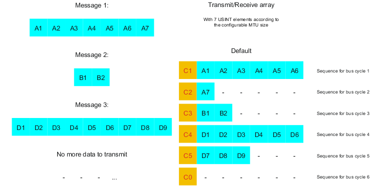
Fig.: Transmit/Receive array (default)
First, the messages must be split into segments. In the default configuration, it is important to ensure that each sequence can hold an entire segment, including the associated control byte. The sequence is limited to the size of the enable MTU. In other words, a segment must be at least 1 byte smaller than the MTU.
MTU = 7 bytes → Max. segment length = 6 bytes
•Message 1 (7 bytes)
•First segment = Control byte + 6 bytes of data
•Second segment = Control byte + 1 data byte
•Message 2 (2 bytes)
•First segment = Control byte + 2 bytes of data
•Message 3 (9 bytes)
•First segment = Control byte + 6 bytes of data
•Second segment = Control byte + 3 data bytes
•No more messages
•C0 control byte
A unique control byte must be generated for each segment. In addition, the C0 control byte is generated to keep communication on standby.
C0 (control byte 0) |
C1 (control byte 1) |
C2 (control byte 2) |
||||||
- SegmentLength (0) |
= |
0 |
- SegmentLength (6) |
= |
6 |
- SegmentLength (1) |
= |
1 |
- nextCBPos (0) |
= |
0 |
- nextCBPos (0) |
= |
0 |
- nextCBPos (0) |
= |
0 |
- MessageEndBit (0) |
= |
0 |
- MessageEndBit (0) |
= |
0 |
- MessageEndBit (1) |
= |
128 |
Control byte |
Σ |
0 |
Control byte |
Σ |
6 |
Control byte |
Σ |
129 |
Table: Flatstream determination of the control bytes for the default configuration example (part 1)
C3 (control byte 3) |
C4 (control byte 4) |
C5 (control byte 5) |
||||||
- SegmentLength (2) |
= |
2 |
- SegmentLength (6) |
= |
6 |
- SegmentLength (3) |
= |
3 |
- nextCBPos (0) |
= |
0 |
- nextCBPos (0) |
= |
0 |
- nextCBPos (0) |
= |
0 |
- MessageEndBit (1) |
= |
128 |
- MessageEndBit (0) |
= |
0 |
- MessageEndBit (1) |
= |
128 |
Control byte |
Σ |
130 |
Control byte |
Σ |
6 |
Control byte |
Σ |
131 |
Table: Flatstream determination of the control bytes for the default configuration example (part 2)