X20CM4800X - Data sheet V1.04
If the way messages are structured is changed, then the way data in the transmit/receive array is arranged is also different. The following changes apply to the example given earlier.
If MultiSegmentMTUs are allowed, then "open positions" in an MTU can be used. These "open positions" occur if the last segment in a message does not fully use the entire MTU. MultiSegmentMTUs allow these bits to be used to transfer the subsequent control bytes and segments. In the program sequence, the "nextCBPos" bit in the control byte is set so that the receiver can correctly identify the next control byte.
Example
3 autonomous messages (7 bytes, 2 bytes and 9 bytes) are being transmitted using an MTU with a width of 7 bytes. The configuration allows the transfer of MultiSegmentMTUs.
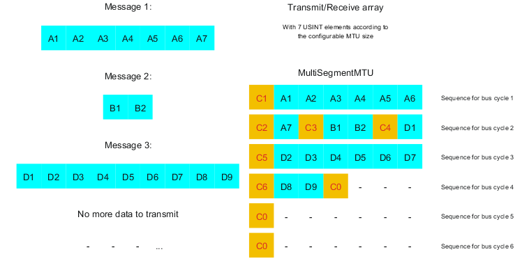
Fig.: Transmit/receive array (MultiSegmentMTUs)
First, the messages must be split into segments. As in the default configuration, it is important for each sequence to begin with a control byte. The free bits in the MTU at the end of a message are filled with data from the following message, however. With this option, the "nextCBPos" bit is always set if payload data is transferred after the control byte.
MTU = 7 bytes → Max. segment length = 6 bytes
•Message 1 (7 bytes)
•First segment = Control byte + 6 bytes of data (MTU full)
•Second segment = Control byte + 1 byte of data (MTU still has 5 open bytes)
•Message 2 (2 bytes)
•First segment = Control byte + 2 bytes of data (MTU still has 2 open bytes)
•Message 3 (9 bytes)
•First segment = Control byte + 1 byte of data (MTU full)
•Second segment = Control byte + 6 bytes of data (MTU full)
•Third segment = Control byte + 2 bytes of data (MTU still has 4 open bytes)
•No more messages
•C0 control byte
A unique control byte must be generated for each segment. In addition, the C0 control byte is generated to keep communication on standby.
C1 (control byte 1) |
C2 (control byte 2) |
C3 (control byte 3) |
||||||
- SegmentLength (6) |
= |
6 |
- SegmentLength (1) |
= |
1 |
- SegmentLength (2) |
= |
2 |
- nextCBPos (1) |
= |
64 |
- nextCBPos (1) |
= |
64 |
- nextCBPos (1) |
= |
64 |
- MessageEndBit (0) |
= |
0 |
- MessageEndBit (1) |
= |
128 |
- MessageEndBit (1) |
= |
128 |
Control byte |
Σ |
70 |
Control byte |
Σ |
193 |
Control byte |
Σ |
194 |
Table: Flatstream determination of the control bytes for the MultiSegmentMTU example (part 1)
Warning!
The second sequence is only permitted to be acknowledged via SequenceAck if it has been completely processed. In this example, there are 3 different segments within the second sequence, i.e. the program must include enough receive arrays to handle this situation.
C4 (control byte 4) |
C5 (control byte 5) |
C6 (control byte 6) |
||||||
- SegmentLength (1) |
= |
1 |
- SegmentLength (6) |
= |
6 |
- SegmentLength (2) |
= |
2 |
- nextCBPos (6) |
= |
6 |
- nextCBPos (1) |
= |
64 |
- nextCBPos (1) |
= |
64 |
- MessageEndBit (0) |
= |
0 |
- MessageEndBit (1) |
= |
0 |
- MessageEndBit (1) |
= |
128 |
Control byte |
Σ |
7 |
Control byte |
Σ |
70 |
Control byte |
Σ |
194 |
Table: Flatstream determination of the control bytes for the MultiSegmentMTU example (part 2)
Segments are limited to a maximum of 63 bytes. This means they can be larger than the active MTU. These large segments are divided among several sequences when transferred. It is possible for sequences to be completely filled with payload data and not have a control byte.
Information:
It is still possible to subdivide a message into several segments so that the size of a data packet does not also have to be limited to 63 bytes.
Example
3 autonomous messages (7 bytes, 2 bytes and 9 bytes) are being transmitted using an MTU with a width of 7 bytes. The configuration allows the transfer of large segments.
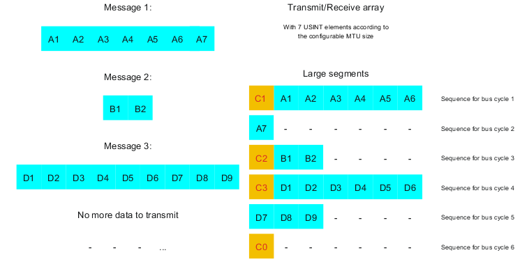
Fig.: Transmit/receive array (large segments)
First, the messages must be split into segments. The ability to form large segments means that messages are split up less frequently, which results in fewer control bytes generated.
Large segments allowed → Max. segment length = 63 bytes
•Message 1 (7 bytes)
•First segment = Control byte + 7 bytes of data
•Message 2 (2 bytes)
•First segment = Control byte + 2 bytes of data
•Message 3 (9 bytes)
•First segment = Control byte + 9 bytes of data
•No more messages
•C0 control byte
A unique control byte must be generated for each segment. In addition, the C0 control byte is generated to keep communication on standby.
C1 (control byte 1) |
C2 (control byte 2) |
C3 (control byte 3) |
||||||
- SegmentLength (7) |
= |
7 |
- SegmentLength (2) |
= |
2 |
- SegmentLength (9) |
= |
9 |
- nextCBPos (0) |
= |
0 |
- nextCBPos (0) |
= |
0 |
- nextCBPos (0) |
= |
0 |
- MessageEndBit (1) |
= |
128 |
- MessageEndBit (1) |
= |
128 |
- MessageEndBit (1) |
= |
128 |
Control byte |
Σ |
135 |
Control byte |
Σ |
130 |
Control byte |
Σ |
137 |
Table: Flatstream determination of the control bytes for the large segment example
Large segments and MultiSegmentMTU
Example
3 autonomous messages (7 bytes, 2 bytes and 9 bytes) are being transmitted using an MTU with a width of 7 bytes. The configuration allows transfer of large segments as well as MultiSegmentMTUs.
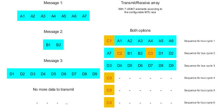
Fig.: Transmit/receive array (large segments and MultiSegmentMTUs)
First, the messages must be split into segments. If the last segment of a message does not completely fill the MTU, it is permitted to be used for other data in the data stream. Bit "nextCBPos" must always be set if the control byte belongs to a segment with payload data.
The ability to form large segments means that messages are split up less frequently, which results in fewer control bytes generated. Control bytes are generated in the same way as with option "Large segments".
Large segments allowed → Max. segment length = 63 bytes
•Message 1 (7 bytes)
•First segment = Control byte + 7 bytes of data
•Message 2 (2 bytes)
•First segment = Control byte + 2 bytes of data
•Message 3 (9 bytes)
•First segment = Control byte + 9 bytes of data
•No more messages
•C0 control byte
A unique control byte must be generated for each segment. In addition, the C0 control byte is generated to keep communication on standby.
C1 (control byte 1) |
C2 (control byte 2) |
C3 (control byte 3) |
||||||
- SegmentLength (7) |
= |
7 |
- SegmentLength (2) |
= |
2 |
- SegmentLength (9) |
= |
9 |
- nextCBPos (0) |
= |
0 |
- nextCBPos (0) |
= |
0 |
- nextCBPos (0) |
= |
0 |
- MessageEndBit (1) |
= |
128 |
- MessageEndBit (1) |
= |
128 |
- MessageEndBit (1) |
= |
128 |
Control byte |
Σ |
135 |
Control byte |
Σ |
130 |
Control byte |
Σ |
137 |
Table: Flatstream determination of the control bytes for the large segment and MultiSegmentMTU example